Four Steps To Enhance High Frequency Communications
Using wideband technology high frequency communications can offer commensurate or increased data throughput over satellite communications in normal or satellite-denied environments to augment command and control beyond line-of-sight communications needs.
High frequency communications can be the A, C or E of every primary, alternate, contingency and emergency (PACE) plan and might become the P in certain circumstances.
PACE refers to the primary, alternate, contingency and emergency communications planning. On numerous occasions, the satellite-denied environment has become an actuality, and commanders must be able to plan—and practice—accordingly. When Russian forces invaded Ukraine and jammed or spoofed communications and navigation, high frequency (HF) solutions would have been an ideal primary communications plan.
Successful HF requires three components: selection of the proper frequencies for the mission, correct programming of the radios and choosing the right antennas for the available link(s).
Frequency selection is critical and will depend on the mission, location, time of day and time of year. The seasons and locations affect the atmospheric ionization because of the varying distance of the sun to certain areas of the earth and varying angle of radiation on those areas. The ionosphere consists of multiple layers. The height of the F2 layer increases greatly in the summer and decreases in winter. Also, the F2 ionization density is stronger and rises earlier in the day during winter.
In simple terms, HF range may be divided into three distances: near vertical incidence skywave (NVIS), medium and long range. Arguably these could be defined as zero to 400 miles, 400 to 1,000 miles and 1,000 to 2,500 plus miles.
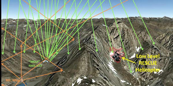
NVIS signals travel nearly straight up to strike the ionosphere and return to earth. The effect is important when working in a battle zone and in mountainous or jungle environments and will be the predominant frequency range for battlefield communications because it is the zone where a commander should obtain the most possible frequencies. Midrange and long-range communications may be necessary for command and logistics functions.
HF signals travel skyward and reflect off of the four ionosphere layers existing between 75 to 300 miles above the earth. That is what allows HF to bounce back down on the reverse side of a nearby mountain. These layers are activated by solar activity and come and go somewhat unpredictably, causing constant variations in the frequencies so that they may or may not work.
That means those frequencies may or may not link, which is why it is necessary to have multiple frequencies from which the radio can choose. One frequency may work for a time, then drop out. The alert operator will notice the diminished connection and return to reestablishing a new link, possibly bouncing off another ionosphere layer.
If properly programmed, frequencies that match the required ranges, automatic link establishment (ALE), the worldwide standard for digitally establishing and maintaining HF communications, allows the radio to select a new frequency and continue to march. Frequency selection technology incorporated in the current HF radios—especially 3G—allows the radio to probe the propagation between stations to select the optimum operating frequency and establishes the link for the operator automatically. Free prediction programs, such as the Voice of America Coverage Analysis Program, provide the user with fairly reliable frequency planning. Learn it, practice it and use it.
NVIS frequencies may be described generally as 2-10 MHz; midrange as 8-18 MHz, and long-range 15-30 MHz. However, openings in any part of the HF band can and do occur at any time, and ALE may then link. The low-end frequencies have longer wavelengths and will reflect off those ion levels when directed straight up at them, whereas the higher ones will blow right through. With attempts at longer distance connections using higher frequencies, the takeoff angle of the signal should be longer and lower so that the signals do not strike the ionosphere layers directly.
Instead, they will reflect much like a stone skipping off a pond surface. In essence, normally, the longer the connection, the higher the frequency and the lower the angle of takeoff from the antenna. And, as those ionosphere rings are constantly changing from active to inactive, a radio must have the ability to change with them, making ALE a critical capability.
Today’s military radios have ALE capabilities allowing them to search all programmed frequencies and select a suitable one to connect to another radio with an identical set of programmed frequencies. Programming before beginning an operation is critical and is a major failure point in today’s HF communications. If possible, conduct side-by-side bench testing of radios with dummy loads, which are electrical devices that simulate antennas, so programming and operation can be checked in the shop prior to deployment.
Too frequently, trying to fix it or work it out later with a cellphone is a no-go because cellphone capabilities are often nonexistent in a contested combat zone. Program the proper frequencies first and then test the radios against one another before going to the field.
Lastly, have the right antenna for the mission. All antennas are not equal and are not designed for every job. The antenna that came with the radio is not necessarily the best for every situation. Antennas are designed for different propagation capabilities.
For example, stick or whip antennas are not generally NVIS designed, transmitting signals 360 degrees in a very long and low pattern, usually for longer ranges. Some NVIS is attainable by bending the whip over, as is common on today’s vehicle setup, but the signal strength off the end of the antenna is less, so the direction intended to transmit must be considered. Every time the vehicle or antenna direction is changed, the NVIS pattern changes, providing less than reliable links. Mobile vehicle links can be more difficult.
Wire dipole-type antennas may be configured for NVIS, medium- or long-range, and some have all three capabilities without any adjustment. The drawback is that they must be erected and recovered during a stop; however, this may only take a trained operator about five minutes with new mast technology.
A low-height flat dipole antenna sends signals virtually straight up (NVIS). By raising the balun—an electrical device that in this case matches a radio to coax/antenna—the transmitted waves are less vertical and the glance off the ionosphere and the return to Earth is at a greater, midrange, distance.
Even longer distances may be reached by hoisting the antenna balun much higher and creating a more serious downward slope to the wires, thus a lower angle of takeoff for the signal.
Remember, however, when that configuration is used, NVIS is usually all but lost. Adjusting the balun height up and down, which takes seconds, may locate a sweet spot where everything works—NVIS, medium- and long-range. Practice is the key, and every day is different. A very long-range directional link may be made by hoisting one end of the antenna wire to the top of a mast, balun in the middle, and the far end pegged down to the ground in the appropriate direction of the receiving station. This technique is specifically used in low probability of intercept and low probability of detection linking using very low power settings. In the inverted “V” configuration, there is both NVIS and range.
Finally, tuned versus broadband antennas. Because each frequency has a different resonant wavelength, no antenna matches every wavelength perfectly. Simply described, a tuner/coupler is an electronic device that attempts to provide a 50-ohm load—a perfect antenna—to the transmitter, indicating that the correct length of antenna for resonance exists at a given frequency in the HF spectrum, thereby allowing full or near-full power to the antenna to radiate.
Another type of antenna, a broadband antenna, utilizes a given length of wire, a balun and a resistive load for the same purpose. Since the military has access to the entire HF band and not just slices of it, a broadband antenna may be preferred. That’s because the tuner, a potential failure point, is eliminated, and the antenna accepts all frequencies for instant transmission.
This feature can speed up ALE links because a tuner/coupler requires extra time (usually milliseconds to seconds) to match the frequency for the radio, even if the frequencies are in the tuner memory. The amount of extra time depends on the number of preprogrammed frequencies and those saved frequencies in the coupler/tuner. Five preprogrammed frequencies, for example, will take less time than 20.
Should a tuner/coupler fail, the user can shut down the tuner in the radio and keep operating. As with any system, a broadband antenna also has a drawback. For some frequencies selected, even though the antenna transmits satisfactorily on that frequency, they will be at a somewhat reduced power. That power is lost as heat in the load instead of the radio. This means that the true power output off of the antenna may be less than maximum; however, this is generally insignificant in battlefield operations since the intended links are not far away in a battlespace scenario.
It is important to have an antenna that can change configurations quickly to achieve different results, especially for on-the-move operations. A proper antenna should be able to provide NVIS, medium and long distances with simple changes in configuration. Wire dipole antennas are also easily field repairable, unlike whips or tuner/couplers. Broadband antennas can provide continuous operations as a failsafe against tuner/coupler failures while also being used seamlessly with tuner/coupler systems. Some designs take up one-half less space in the field.
Just remember PPTC: Pick the right frequencies. Program the radios correctly. Test them against each other before any deployment. Choose the right antennas for the job. These four steps ensure HF will be a highly successful and faithful asset.
Chief Warrant Officer 4 Kurt Stephens, USCG (Ret.), is an avionics officer with 30 years of military service in aviation, shipboard and land systems and 14 years of communications experience in the corporate world as a systems engineer, staff engineer and field engineer. He is currently the CEO of White Wolf Systems.
Lt. Col. Bill Whittington, USA (Ret.), is the marketing director of White Wolf Systems. He is a former infantry office and airborne ranger with two Vietnam combat tours and 27 years in HF communications with an emphasis on antenna design and installation.


Comments