Airborne Gateway Connects Far-Flung Battlefield Forces
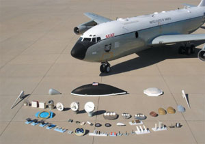 |
| Special-purpose antennas easily can be installed in existing panels, under existing radomes, or behind an optical window on the U.S. Air Force Research Laboratory’s (AFRL’s) Command, Control, Communications, Computers and Intelligence (C4I) Airborne Testbed. Various combinations of 30 to 60 antennas can be flown on the aircraft to cover frequencies from kilohertz to terahertz. |
Air Force platform’s terminals, antennas support varied communication networks.
A unique flying antenna testbed plays a significant role in the development and integration of battlefield information networks and communications nodes. Moreover, this aircraft’s primary function is to support airborne communications transition to production and fusion into new command and control networks.
Based at Wright-Patterson Air Force Base, Ohio, the U.S. Air Force Research Laboratory’s (AFRL’s) C-135E testbed aircraft is a mainstay of communications developmental programs for all the U.S. armed services and some allied nations, Helen Demers points out. She is a senior engineer and airborne communications program manager, operating within the platform connectivity branch of the information grid division in the laboratory’s Information Directorate.
The AFRL’s Command, Control, Communications, Computers and Intelligence (C4I) Airborne Testbed, or ACAT, is slated to conduct flight demonstrations with the advanced Optical Radio Frequency (RF) Combined Link Experiment (ORCLE), Demers reveals. The Defense Advanced Research Projects Agency is developing ORCLE as a revolutionary approach to communications. This program is structured to demonstrate a prototype system that combines laser and RF communications into a single networked system to provide compact, robust, high-bandwidth, mobile communications to military forces.
ORCLE combines the high-data-rate capability of free-space laser communications, the high reliability of RF communications and clever network management. This technology arrangement ensures high-quality, reliable networked communications, even if atmospheric conditions or physical obstructions affect some of the links. The optical datalink is designed to communicate at 2.5 gigabits per second and the RF tactical common datalink at 45 megabits per second.
Airborne ORCLE network demonstrations in fiscal 2006 will include the use of air-to-air and air-to-ground acquisition, pointing and tracking algorithms, and communications through obscurants that provide applicability to follow-on transformation communications. Also involved are hybrid protocols for networking that use differentiated services and multiprotocol-label-switching-based traffic provisioning.
A gateway ORCLE demonstration will include two free-space optical terminals. A silver terminal with a reflective gimbaled telescope will be located behind the optical window in the aircraft’s cargo door. A gold terminal, using a Risley-prism system, will be located under the floor, flush with a window in the aircraft. There also are two RF terminals for the demonstration. One is linked to a tactical common datalink with an omni antenna and the other to a tactical common datalink with a sectored horn array antenna. A ground-based bronze terminal will use a hybrid free-space optical and RF antenna and a 45-megabit-per-second modulating retro reflector.
After recent successful airborne battlefield network and joint interoperability demonstrations, ACAT also is scheduled to participate in the U.S. Defense Department’s Transformational Communications Airborne Technology System (TCATS) demonstration, Demers continues. This later TCATS development involves validation of high-bandwidth RF and optical communications links—both air-to-air and air-to-ground laser communications technologies.
The TCATS program encompasses integration of a multiplatform tactical common datalink and laser communications terminal into a central router via a fiber optic backbone onboard the aircraft. Additionally, this airborne demonstration implements management protocols for priority, precedence, high throughput and assured access. The TCATS demonstration integrates sensor data, Global Broadcast System (GBS) communications, tactical targeting network technologies and a family of airborne terminals, according to Demers. The concept is to demonstrate network-centric command and control successfully.
Joint collaboration is part of the TCATS program involving the National Aeronautics and Space Administration’s Sensor Web. This includes high spatial and temporal resolution sampling of atmospheric phenomena and testing of new remote-sensing technologies. The demonstrations also support the Air Force’s high-bandwidth airborne intelligence, surveillance and reconnaissance sensors, simultaneously connecting multiple inter-platform links, Demers observes.
“ACAT operates with more than 30 antennas positioned every five feet along the top and bottom of the aircraft, enough to make the platform look like a porcupine,” Allen Johnson notes. He is a senior AFRL consultant with Dayton-based SelectTech Services Corporation. “With the move to joint operations, the aircraft is configured to handle U.S. Army, Navy and Air Force communications systems testing in a variety of frequencies and waveforms.
“Because of the unique environments in which each service must operate, different communications systems are being developed and fielded that function in distinct frequency bands,” Johnson maintains. “ACAT’s suite of antennas covers frequency bands from kilohertz to terahertz: medium, high, very high (VHF), ultrahigh (UHF), extremely high frequencies (EHF); L band, S band, Ku band, Ka band and lasers.”
AFRL’s platform connectivity branch is the technical lead for the transformational communications air network layer. ACAT provides a low-cost, low-risk development platform in the search for the joint airborne network tactical edge, Demers explains. Focused on evolving military communications, the C4I testbed will provide a backbone for air-to-air communications and the Global Information Grid with persistent RF links between aerial and ground-based platforms, including sensor readouts from 10 to 300 megabits per second, she adds.
Satellite terminal development is a branch strength, Demers continues. This branch earlier combined with AFRL’s datalinks group, and ACAT contains a variety of datalinks such as UHF Link 16, along with a General Dynamics software-defined precursor Joint Tactical Radio System (JTRS). A number of structural modifications to aircraft provides holes for various antenna systems, doublers, optical windows and pressurized wave guides running through fuel cells to connect antenna dishes on the bottom of the fuselage. “The aircraft is optimized for communications developmental testing. We never get rid of a hole for an antenna; we just cover it over,” she adds.
 |
| The interior cabin of the flying testbed is lined with C4I equipment racks, workstations and consoles. The primary function of the AFRL’s aircraft is to support development of airborne communications systems and transition to inventory products. |
The C4I flying testbed focuses on customer communications systems. Test equipment and work centers are located throughout the aircraft in racks and consoles, Demers says. There are multiple frequencies and antennas already available to customers, and testbed modifications are accomplished by AFRL to control cost and schedule. Aircraft configuration allows easy installation with lift-on, lift-off capability for communications equipment. A 30-inch optical window is mounted in the cargo door, and the wave-guide is in a cavity aft of the nose gear, with low-loss cable and conduit available. The avionics bay area is forward of the nose gear, accessible through the nose hatch.
The backbone optical fiber local area network on the aircraft uses wave division multiplexing (WDM) technology for multiple channels, enabling it to function as a network-centric platform. WDM interconnects onboard communications systems and workstations, connects C4I applications software and hardware for flight demonstrations, minimizes system configuration changes and consolidates data handling, Demers relates. Integration of next-generation WDM technology involves installation of L3 photonics technology. This new backbone’s miniaturized components provide higher data handling capabilities to support ORCLE and TCATS requirements, she discloses.
“The TCATS program involves the next-generation EHF satellite system, and we are working with terminals that will support this effort. ACAT is playing a major role by bolstering satellite terminal developments and demonstrations necessary for transition to the inventory,” Demers remarks. “We have been involved in all of the EHF satellite terminal development work, along with GBS terminals using commercial frequencies and higher Ka-band terminals for government communications. We also operate with commercial digital television, moving from asynchronous transfer mode to Internet protocol communications.”
“Using the software-defined radio for JTRS, we patch anything to anything, and the system automatically handles all of the translations and transitions.” An example Demers uses involves the Army’s Single Channel Ground and Airborne Radio System (SINCGARS). “As long as SINCGARS network nodes have line of site to the aircraft, the terminals connect the sites seamlessly as if each is next door,” she emphasizes.
“During a live-fire exercise last summer at Fort Knox, Kentucky, the Army used ACAT as an overhead asset to connect all their communications systems on the ground,” Johnson relates. “This demonstration, known as the Assistant Secretary of the Army for Acquisition, Logistics and Technology (ASSALT), involved a variety of radios and systems operating throughout the spectrum. ASSALT flights clearly proved the effective interaction of battlefield systems and how technology can improve warfighting capabilities.”
The ASSALT exercise involved the software-defined radio as a JTRS surrogate to demonstrate gateway functions on the aircraft. These capabilities included SINCGARS-to-SINCGARS translation and extension, UHF-to-EHF translation for Blue Force Tracking and live-fire image transmissions. Military-to-civilian frequency conversions involved those between SINCGARS and APCO 25 UHF frequency modulation waveforms and Link-16 network controllers for ground terminals, Johnson maintains.
ACAT was configured to act as a communications node, relaying SINCGARS VHF links between widely scattered Army ground units operating at different frequencies. The system received Blue Force Tracking data on UHF links, processed the data and passed it back to a ground command center via EHF Milstar satellite, using the airborne command post terminal, Johnson asserts. Battle damage assessment photographs were sent to the ground via the UHF line-of-sight link, and threat data were transmitted to the ground via L-band line-of-sight Link 16.
ACAT flights over Hawaii involved a joint tactical force Wide Area Relay Network (WARNET) demonstration, using JTRS surrogates and existing legacy communications equipment to provide connectivity, according to Johnson. The concept called for interfacing and translating among all of the services’ tactical command and control systems to prove joint interoperability and collaboration. The exercise demonstrated system management, providing input to concept of operations, tactics, techniques and procedures, he claims.
During WARNET, this airborne gateway connected tactical units from the Army, Navy, U.S. Marine Corps and Air Force via VRC-99 line-of-sight radio and network media. This capability enabled joint war planning and execution between diverse tactical sites. Live friendly blue force tracks were received from land-mobile and sea-based units by the aircraft’s ATR-507 receiver, fed through a Maricopa post processor and then transmitted via VRC-99 radio to a processing center on Oahu.
These tracks were combined with information from other sources and sent back to the aircraft via VRC-99. Information received was processed through the command and control translator database, and updated tracks were sent to a Battle Operations Support System (BOSS) laptop for retransmission. BOSS routed the tracks to the onboard fighter data Link-16 system for transmission to the Pacific Missile Test Range on Kauai. BOSS also routed tracks to the digital modular radio for transmission over a Link-16 satellite communications extension to a UHF groundstation in the continental United States equipped with a BOSS laptop.
ACAT also provided a platform for joint GBS and Australia’s Theater Broadcast System (TBS) to demonstrate interoperability in a coalition environment. The concept involved airborne reception of TBS signals as a mission-planning tool, Johnson recounts. This approach involved a Ku-band Luneberg lens for TBS reception, an EHF Milstar antenna modified to receive GBS input, multiple ground locations and aircraft to receive real-time broadcasts. Satellite links to airborne terminals included the Ku-band PAS-8 and the UHF Follow-On-8. Information products provided included a common operational picture, imagery, video and command briefings.
In a demonstration of the Army’s En Route Mission Planning and Rehearsal System, the aircraft was configured to receive wideband intelligence data via a surrogate GBS Ku-band satellite link, forwarding it to an Army C-130 command aircraft, Johnson stresses. “Transmitting via line-of-sight S band, the flying local area network allowed the airborne commander to adjust his battle plan until just prior to reaching the jump point. The UHF line-of-sight link also provided flight coordination between ACAT and the Army’s aircraft.”
ACAT has two primary wideband antenna installations that provide the aircraft with a unique satellite communications capability. There are six interchangeable wideband antennas covering primarily Ku band and Ka band, which can be used in separate aircraft installations, Johnson confirms. Three of these antennas include transmission functions that allow megabit-data-rate transmission over satellite channels to relay data nearly anywhere in the world. Indeed, he concludes, ACAT digitally connects today’s battlefield.
Web Resource
Air Force Research Laboratory Platform Connectivity Branch: www.rl.af.mil/div/IFG/IFGD/IFGD_home.html


Comments