Britain Trials Sea Technology On Dry Land
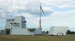 |
The HMS Queen Elizabeth aft island mock-up is being built on the Isle of Wight. |
The Royal Navy is creating an island on an isle in an effort to de-risk advanced communications systems early, easily and with less expense than traditional means. As
Approximately 100 radars and antennas will be grouped on the two carriers’ aft and forward islands, making for a variety of potential problems. The aft island is particularly complex, complicated by a further challenge to integrate a medium-range radar close by a pole mast that hosts an array of transmitting and receiving aerials. In the past,
The carriers will be the largest ships in the Royal Navy—65,000 tons, compared to the 22,000 tons of the current carriers—and equipped with leading-edge technology. The ships will accommodate nearly double the amount of communications equipment on the vessels already in the fleet and will incorporate communications equipment and capabilities more advanced than those in service now. “What we’ve tried to do is balance high technology with getting the program out on time and on budget,” Cdr. Petitt says.
The commander explains that the systems are not taking a vast technological leap forward, but that the way developers are joining the systems together is a step improvement on current systems. “The Blown Fiber system is one that is used widely in office blocks but the way we are implementing it onboard is new; it will provide great flexibility in the future,” he says.
The carriers will include 1,740 kilometers (1,081 miles) of fiber optic cable to support voice and data services for 1,500 people onboard. He explains that it took developers time to reach the right capacity, and they had a large topside challenge in trying to fit the aerials on the small amount of upper deck real estate. Another issue is the number of component technologies. The ships include 60 subsystems and 14,000 items of equipment. The antennas and aerials for radars and other systems will be mounted on the vessels’ two islands, which are situated 79 meters (259 feet) apart.
Steve Dowdell, mission system director for the Aircraft Carrier Alliance (ACA) and a BAE Systems Insyte employee, says, “This is probably the first integrated electronic mission system going onboard a carrier anywhere.” The aircraft control center will run night and day, and information technology systems will provide capabilities to everyone on the ship.
To accommodate the scope of the project, the Aircraft Carrier Alliance (ACA) was formed to work on the Queen Elizabeth carriers. Team members include BAE Systems Insyte, BVT Surface Fleet, Thales
Cdr. Petitt touts the ACA as a benefit that reduces communications problems enormously. He likens the approach to building a house: People would not have a builder construct their home without being involved in the process, yet shipbuilding programs have operated in that fashion for years. The approach to the carrier construction has been a concerted effort to proceed differently and make the Navy part of the solution, enabling earlier de-risking.
Early work is needed on the ships because of design considerations. Steve Brown, a BAE Systems Insyte employee and mission systems integration manager for the ACA, says the Queen Elizabeth-class’s islands are small considering the size of the overall platform, creating an electromagnetic environment (EME) challenge because of the constrained upper deck area for placing the forest of antennas. The capabilities enabled by the equipment are essential on an aircraft carrier because of the signal communications requirement to ensure contact with the in-flight aircraft, consort group, headquarters and land forces. “It’s an awful lot of communications to happen with not a lot of space to put those antennas,” Brown explains. “That means the islands, especially the aft of the two islands, are very densely packed, and we’ve had to incorporate technologies that are new to the Royal Navy to allow these antennas to be located so close together.”
To prepare for the potential problems caused by the many systems and the jam-packed aft island, developers embarked on a series of modeling techniques. First, they created models on paper and then moved to computer versions. The modeling activities alerted program personnel to the optimum arrangement of the antennas in relation to the pole mast and given the design constraints. Part of the test activities will validate the modeling where one system might impact another.
An empirical assessment allowed developers to locate the antennas in places they believed would be appropriate based on previous experience. They then incorporated computer modeling that used pattern completers looking at specific areas they thought might have issues. After that, personnel could modify positions or adjust the structure of the antennas. Though the results for the forward island were satisfactory, the crowded nature of the aft island, in conjunction with the position of the pole mast, resulted in some residual risk.
Another BAE Systems Insyte employee, Peter Jewson, missions systems engineering manager for the ACA, says questions exist over whether mathematical modeling alone is accurate enough to determine what happens in the very near region where some of the critical interactions take place. “Therefore the activity itself will expose whether that is an accurate prediction to allow this critical design to be stabilized,” he explains. The work done on the mock-up is only one level of testing; the actual integration communications suite goes on to be functionally tested for requirements-proven purposes later. “So we’ve actually got two phases of testing,” Jewson elaborates. One makes sure the EME skyline is categorized correctly; the second enables later functional tests.
To mitigate the pole mast and other potential problems, program officials built the metalwork mock-up at the BAE Systems Insyte facility at
The mock-up only re-creates the top slice of the aft island from the 05 deck and above. On it, developers can locate the antennas and power the communications equipment to confirm that systems work and that the test results match what modeling predicted. The mock-up assessments also ensure no fundamental problems exist with the arrangement of the antennas. “The whole rationale of starting early is because we want to confirm that that arrangement is viable prior to starting manufacture of the full platform items,” Brown says.
De-risking work on an array of antennas on top of the superstructure has been an ongoing process. According to Dowdell, “We did some work starting a couple years ago to say, ‘Actually can we get those antenna close enough together? Can we get the power out to have all those simultaneous circuits talking to all the aircraft that we need?’” When they began, developers were unsure of the outcome so they commenced on the de-risking early to resolve the crown of thorns antenna ring. Throughout the design efforts, developers are addressing the various technical risks piecemeal, identifying potential problems and trying to mitigate them as early as possible. “So that’s our general mantra if you like,” Dowdell says. “Do it little and often, and do it as early as possible.”
 |
Computer-generated image of the Queen Elizabeth-class aircraft carriers’ two islands as viewed from the flight deck. |
According to Cdr. Petitt the mock-up enables the team to get to the crux of the problem before finalizing the upper deck de-risking. “To be frank, the whole of the aft island is relatively cluttered, and we just wanted to assure ourselves that we put all of the antennas in the right place and that they all worked together, and that they all worked together with some surety,” he explains.
The viability of the aft-island arrangement should be confirmed by mid-2010. Success at
Most of the antennas being fitted on the mock-up are the actual platform equipment. Brown explains that the ACA is not investing in extra sets of equipment but will use the items intended for the final ships. After testing, the pieces will be refurbished if necessary and then go into storage until installation. The equipment will be added onto the mock-up bit by bit. Brown states that developers would have preferred to have all the antenna equipment available at the beginning so they could bolt it down and start full-on testing, but explains that that approach is not a practical test program. Some contracts are too new for that arrangement to work so the developers are using a phased-test program.
The philosophy of identifying possible risks early in the carrier construction extends beyond the work that is being done on the aft island. During the design of the bridge, developers created a plywood mock-up of the plan endorsed by the various involved parties, only to find out the size was inhibiting. After resolving that issue, personnel began focusing on technologies such as the command, control, communications, computer, intelligence, surveillance, reconnaissance mission suite. Part of the technical de-risking involved running a series of scenarios to ensure everyone involved was on the same page.
Cdr. Petitt explains the plan allows all involved to understand different requirements sets so they can deliver a working warship. He adds that as developers walk through the synthetic environments, whether those are physical mock-ups or computer-generated simulations, they will replace the synthetic with realistic bits of equipment creating a seamless thread to integration. In addition to the savings—costs increase exponentially as the program moves forward, according to the commander—benefits also include a plan to mitigate risk helping to eliminate any delay delivering the ships to the fleet, which he calls “the most important thing.”
In addition to the Royal Navy, the other branches of the
He explains that the navy is researching how to integrate systems and design ships better. In the future, as vessels are built there necessarily will be a need for more migration of systems between old and new ships, he says. More de-risking and testing will happen on older ships and will include a much more through-life approach. “We are looking at, for our future surface combatant, taking a modular view to system architecture and looking at older ships to de-risk new ones,” Cdr. Petitt explains. “While the more coherent approach is new, maturing the combat system on older vessels to align with newer ones is not entirely new.”
The carriers will affect operations in several ways, such as accommodating more and newer aircraft, and, the commander says, “let’s not forget the persuasive factor of parking a large ship off someone’s coast.” Cdr. Petitt expects the new aircraft carrier to be an enormous strategic asset for the Royal Navy. During the development of the advances for the new vessels, personnel have been mindful of the need to interoperate with other
WEB RESOURCES
Queen Elizabeth-class aircraft carriers: www.royalnavy.mod.uk/operations-and-support/surface-fleet/future-ships/queen-elizabeth-class
BAE Systems Insyte: www.baesystems.com/Businesses/Insyte/index.htm


Comments